

 Current position > News detail
『Principle of Velbar flowmeter』Related information(clamp on meter|electromagnetic meter|venturi meterrotameter|orifice meter|ultrasonic flow meter|mass flow meter|coriolis mass flow meter|coriolis flow meter|magnetic flow meter|magmeter flow meter|magflow flow meter|mag meter flow meter|electromagnetic flow meter|vortex flow meter|turbine flow meter|thermal mass flow meter|thermal flow meter|rotameter flow meter)

1. Working principle of pipeline type Velbar flowmeter
The working principle of pipeline type Velbar flowmeter is mainly based on Bernoulli equation. Specifically, fluid dynamics effects: When the fluid flows through the probe of the Velbar flowmeter, due to the special design of the probe, the velocity of the fluid increases in front of the probe, forming a high-pressure distribution area; At the back of the probe, the fluid velocity slows down, forming a low-pressure distribution area. The importance of probe design: The cross-sectional shape, surface roughness, and accurate layout of low-pressure tapping holes of the probe are crucial for the performance and accuracy of the flowmeter. These design factors ensure the stability and accuracy of the low-pressure signal, thereby affecting the measurement results of the flowmeter. The function of multiple pairs of pressure tapping holes: The Velbar uniform velocity flow probe uses multiple pairs of pressure tapping holes, which are buried in the high and low pressure zones according to specific rules. These pressure gauges measure the total pressure and static pressure of the fluid, respectively, to calculate the average velocity and average differential pressure of the fluid, achieving accurate flow measurement. Differential pressure measurement and flow calculation: By measuring the static pressure difference between the high-pressure and low-pressure zones, the average velocity of the fluid can be reflected. According to the Bernoulli equation, the flow rate of the fluid can be further calculated. In summary, the pipeline type flow meter, by cleverly utilizing fluid dynamics principles and combining with the probe structure designed by Jingchun Answering, has
2. Construction of a uniform velocity tube flowmeter
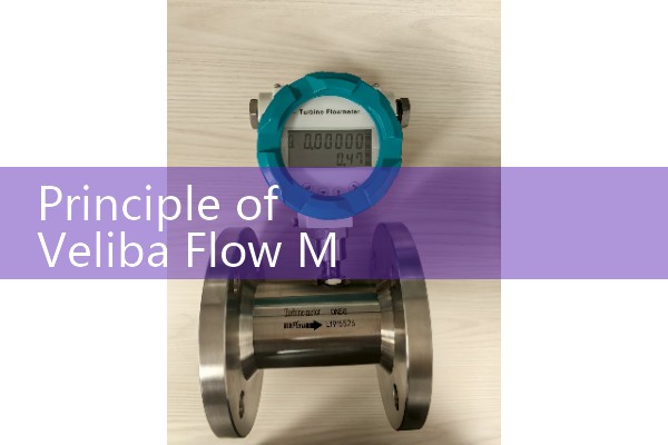
The core of the uniform velocity tube flowmeter construction consists of three parts: an integrated sensor, a differential pressure transmitter, and an accumulator.
. 1. The integrated power bar sensor of the core measurement unit adopts a streamlined dual cavity stainless steel structure, and the surface is roughened to form a turbulent boundary layer. The high-pressure tapping hole is set on the metal curved surface at the front end of the probe, forming a high-pressure barrier to prevent particles from entering; The low-pressure tapping hole is located in front of the side rear airflow separation point, with a double row symmetrical layout that greatly reduces the risk of blockage. The differential pressure transmitter of the signal conversion module precisely senses the pressure difference between the total pressure of the high-pressure chamber and the static pressure of the low-pressure chamber, which directly reflects the average flow velocity of the fluid. After temperature compensation and linearization processing within the module, the standard electrical signal is output to the data processing stage. 3. The data analysis terminal integrator has a built-in fluid density compensation algorithm, combined with operating parameters such as pipe diameter size and Reynolds number, to achieve dual calculation of instantaneous flow rate and accumulated flow rate through Bernoulli equation. The built-in storage unit supports historical data traceability, and the communication interface supports standard protocols