

 Current position > Product detail
『Instruction manual for elliptical gear flowmeter』Related information(clamp on meter|electromagnetic meter|venturi meterrotameter|orifice meter|ultrasonic flow meter|mass flow meter|coriolis mass flow meter|coriolis flow meter|magnetic flow meter|magmeter flow meter|magflow flow meter|mag meter flow meter|electromagnetic flow meter|vortex flow meter|turbine flow meter|thermal mass flow meter|thermal flow meter|rotameter flow meter)
1. Structure and principle of elliptical gear flowmeter
The elliptical gear flowmeter consists of a flow transmitter and a counting mechanism, and its working principle is based on the rotation of the elliptical gear to measure fluid flow.
1. The structure of an elliptical gear flowmeter mainly includes two parts: a flow transmitter and a counting mechanism. Flow transmitter measurement room: The measurement room is equipped with a pair of elliptical gear rotors, which together with the cover plate form a crescent shaped cavity, which serves as the unit of measurement for flow. Sealed coupling: The sealed coupling is used to transmit the rotational motion of the elliptical gear to the counting mechanism while ensuring the sealing of the measuring chamber. Counting mechanism deceleration mechanism: used to slow down the rotational speed of elliptical gears for more accurate counting. Adjustment mechanism: used to adjust the sensitivity of the counting mechanism to ensure the accuracy of measurement. Counter: used to record and display the total amount of fluid passing through the flowmeter. Messenger: used to convert traffic signals into electrical signals for remote monitoring and automatic control. In addition, for use in high-temperature environments, a heat sink can be installed between the transmitter and the counting mechanism to form a high-temperature flowmeter. The working principle of the elliptical gear flowmeter is based on the rotation of the elliptical gear to measure fluid flow. The pressure difference drives the elliptical gear to rotate by the pressure difference between the inlet and outlet of the flowmeter. When fluid flows in from the inlet, it drives the elliptical gear to rotate and
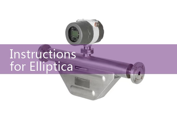
III. Picture Display The following are the structural diagram and working principle diagram of the elliptical gear flowmeter: Through these two pictures, users can have a more intuitive understanding of the structure and working principle of the elliptical gear flowmeter.
. The structural diagram shows the main components of the flowmeter and their connection methods, while the working principle diagram clearly illustrates how the elliptical gear measures fluid flow during rotation. In summary, the elliptical gear flowmeter is a compact and accurate flow measurement instrument. It measures fluid flo